OK, here's how I do it!
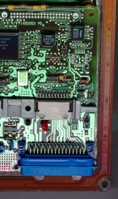
First I crack open the PCM case and extract the screws from the Gray/Blue (T) Side of the PCM. This reveals the printed circuit board. The flash chip is an Intel AN28F512 (automotive temperature range, 512kbit (64kbyte)).
First, I use a small pick to pull some of the silicone sealer goo away from the flash chip, and expose the legs and solder.
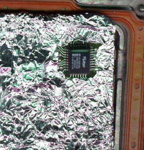
Next, I wrap the board in a piece of aluminum foil that has a hole cut for the flash chip to be the only piece exposed. This will help protect surrounding chips from the heat...
Next, I use a Craftsman Model 129.118010 3-stage heat gun set to the middle temperature (800 degrees F) to heat the flash chip for approximately 20 seconds. I use the small pick to very very very very lightly pry up on the chip. As the solder on the chip melts, the chip begins to lift. Danger, though, if you lift too hard, you'll pull the traces of the printed circuit board up and off. Lift very lightly, let the heat gun do its work. You definitely need a good heat gun, and it may take 30 seconds or so to do it. Danger, that chip gets d*mn hot!
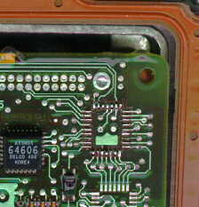
So, here's a shot of just the board... This is AFTER I cleaned the pads with solder wick (put the wick on the pad and heat it with the iron then pull it off). I also used my little metal pick to clean more clear silicon goo off of the board.

OK, now the chip is off, and the pads are clean. I then put a verrry small dab of solder on each pad. Really just enough to give it a small shiny bump. That's all you need. If you have more than a very small amount, get rid of it with the wick and start over. Too much solder will bridge traces... Here's a picture of my dabbed pads.
Next, I take a socket (DigiKey Part Number ED80009-ND) and cut the center base out of it (but don't throw it away!). This allows you easy access to the pins with your soldering iron. I then dab an ever-so-small amount of solder on each pin of the socket (where it will contact the printed circuit board). Then I lay the socket on the board, making sure both the X- and Y- directions are lined up (careful here!) and then I start lightly pushing down on each pin of the socket to melt the pin's solder to the printed circuit board pad's solder. I go around all 32 pins and push each pin down and melt the solder (BTW, my soldering iron is a .8mm chisel tip Hakko 900M-ESD with the 928 temperature controlled dual iron base - that sonuvagun ROCKS! 20 second heat up time...). I also will take some thin thread solder (.010 diameter) and dab more solder on to each pin/pad combination. You might be able to get away with .040 diameter solder, but I wouldn't try any bigger than that.
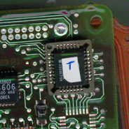
Be sure you pay attention to the orientation of the top of the flash chip (the "Pin 1" designation). The socket has a big "Dot" near the pin 1 designator. On all of these pictures, Pin 1 is at the TOP of the chip.
Here's a picture of my socket mounted to the board. Notice the missing center base.
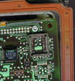
Now, take the center base and put a small dab a of silicone sealant on the backside. Then stick it in the center of the socket to the printed circuit board. (Sorry, I don't have a picture of this one, maybe later). You need to put the base in the socket so that the chip sits at the right height.
So, now, clean the pins on your flash chip. You CAN reuse it. Get all of the excess solder off, as well as the clear goo that is on it. If it's corrupted (a halt in flash programming), you put it in an EEPROM programmer at this time and hit it with a good file (email me if you need one).
Now, insert the chip in to the socket, and label it (Blue/Gray connector side is the T side, Red/Black is the E side). It now looks like this:
Now, you need to test the PCM to make sure it wakes up. Once it's talking, you will need to reprogram it with a known good LT1 image if you are making a repair. The images I have for programming the Flash with an EEPROM programmer are good enough to get the PCM talking again, but they are not going to be able to support driving the car.
So, that's it! Good as new! (well, almost). Be sure you CAREFULLY inspect each pin/leg to make sure it's connected and not shorted with its neighbor. A voltmeter set to ohms and "beep" mode makes for a great way to test these connections.
Good luck!